By Andrew Hodgson
The monopile transition piece is being challenged. Eliminating it from the design may bring benefits to offshore windfarms. TP-less monopiles have now been adopted for a number of live projects and are being considered for many more ongoing developments.
But what benefits does it bring to a project, what does a TP-less monopile look like, and what risks need to be considered in its adoption? This article will examine these questions, drawing from concept studies undertaken by Empire Engineering.
We can’t cover all the technical details and nuances of the design in one single article. The discussion below instead aims to provide a broad overview of the TP-less solution, and help you decide if it is time for you to investigate it further for your next offshore windfarm project.
Why have a Monopile transition piece?
Before diving into removing the transition piece, it is worth reviewing why it has been traditionally included in monopile foundations.
When the offshore wind industry was first gaining traction, it was not possible to achieve the verticality tolerance specified by the WTG suppliers, for the Wind Turbine once the pile had been driven. To compensate, a grouted transition piece, sitting between the monopile and tower, was included. The required alignment tolerance was achieved with the grout taking up the misalignment in the connection between the monopile to TP interface , subsequently giving the tower the required vertical alignment.
In addition to solving the alignment problem, the TP became a very useful piece of structure to connect all manner of appurtenances onto, particularly as it was not being driven and so didn’t experience high installation accelerations. Consequently we ended up hanging off boat landings, anodes, cable hang-offs and platforms.
As the industry has developed, continuous improvements in offshore installation procedures, techniques, and technology have made it possible to achieve this tolerance after driving. This raises the question of whether the TP is still required.
Why change?
The desire to change is driven predominantly by the potential financial benefits that a TP-less solution may bring over a traditional design. These are broadly realised during the O&M phase of the project, but there is also potential to make savings during both fabrication and installation.
Removing the TP eliminates a bolted (or grouted) connection, and subsequently reduces inspection durations. Flange inspection is a costly maintenance operation, particularly for large diameter monopiles that can have in excess of 150 bolts. Reducing the OPEX through elimination of a flange has a significant positive impact on the lifetime cost of the asset.
Fabrication costs are also reduced, though these gains are often marginal with respect to the flange O&M expenditure. The overall steel weight, and consequently the price, remain largely unchanged between traditional and TP-less schemes as (other than the flanges themselves) design elements are rearranged, rather than removed or added.
Opportunities for cost and programme savings can also be made during installation. The multi-component TP-less scheme (detailed below) is made up of a single monopile and four smaller secondary steel items depending on the exact requirements.
There is an opportunity to install the monopile from a large vessel (as standard) and use a smaller, less costly, vessel to mount the secondary items once the monopile has been driven. It may also be possible to use a fleet of secondary steel installation vessels in parallel to make further optimisations to the installation programme.
Studies undertaken by Empire Engineering showed the potential to make approximately 5%-10% cost savings for some sites, although the results are heavily project specific. This saving may appear small but it is on a per monopile basis, and when amplified across all WTGs in a windfarm, the magnitude of reduction is significant.
Talk with a specialist
We've been a part of some of the worlds most exciting and
complicated projects in offshore wind.
If you need more eyes, brains and hands, we're ready to help.
.What might a TP-less design look like?
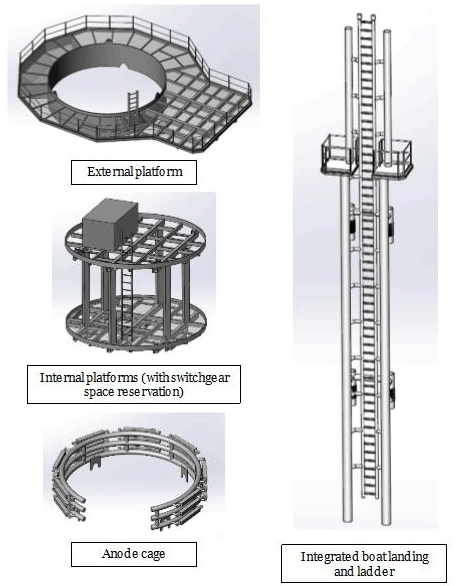
There is no single design to achieve a TP-less foundation. Despite this, the scheme that is gaining the most traction is a multicomponent solution. It is made up of a single primary element (the monopile) and four secondary items as follows:
- Internal platforms (typically airtight and switchgear)
- External platform
- Boat landing
- Anode cage
All components are lowered onto the monopile after driving is complete. The images below show potential solutions for the four secondary components.

TP-less concept study
The boat landing is shown in a single continuous accent. The concept study identified that the traditional split ladder with rest platform may cause issues during installation, achieving verticality when lifted. To address this, a continuous ladder might be proposed. This is only one solution to the lifting problem and other options may exist, which could be investigated at the FEED or detailed design phase.
The multicomponent scheme outlined above uses a GACP corrosion protection strategy. This requires an anode cage to be lowered over the monopile onto mounts below the water line. There is a risk of gouging or damaging the primary structure during installation, and it may be challenging to establish sufficient electrical conductivity with the structure.
The solution has been proposed to show that a GACP strategy is possible, but it is likely that an ICCP scheme might be more suitable for a TP-less design.
What are the risks in going without a Monopile transition piece?
As mentioned, TP-less solutions have been installed on current projects. However, it is still considered novel and with this comes the inherent risks that all new and evolving designs carry.
The total length of the foundation has been traditionally split between the monopile and TP. Removing the TP pushes the full length onto the monopile, resulting in a notable increase in length and weight. This may cause issues during fabrication, load out and installation.
Extra planning and integration with the T&I contractor is needed in order to capitalise on the full savings. This is particularly relevant for pursuing potential optimisations using smaller installation vessels for the secondary steel items.
Risks may also manifest at the design stage of the windfarm. Eliminating the TP results in the driving being performed directly on the monopile WTG interface flange, which could cause design and tolerance issues. There are also a higher number of attachments welded to the monopile. These will be subject to driving loads and will need to be designed to prevent high build-up of fatigue damage under this load.
Conclusion
This article has presented a high-level overview of the key drivers and risks associated with a TP-less monopile design. The TP-less design presented above outlines the TP-less monopile solution which is emerging and the preferred industry design.
It is hoped that the uptake of TP-less designs continues to accelerate. If risks are managed competently, it can provide significant cost and programme optimisations, leading to a more favourable project outcome for all parties involved.
Further Information
Much of the content of this article was presented as a webinar by Empire Engineering as part of the Foundation Ex Tech Sessions. A recording of the session can be viewed on demand at the following link. Other articles, and webinars in the Foundation Ex Tech Session can be found here.
To find out more, please get in touch with the team at Empire Engineering.


